What Is a Three Phase Motor and How Does It Work?

Time:2026-10-29 Author:Isabella
0%

A Three Phase Motor is the quiet workhorse behind many familiar machines: workshop compressors, water pumps, conveyor belts, and factory fans. Its smooth, steady operation can seem almost effortless, yet it depends on carefully coordinated electrical phases and a sturdy mechanical design. Electrical-machines author Stephen J. Chapman describes the three-phase induction motor as “the most common motor in use today.” That prominence comes from practical strengths, including reliable operation, simple construction, and the ability to serve demanding industrial loads. Still, a motor’s popularity does not make every model suitable for every job.

In a three-phase supply, three alternating currents rise and fall at different points in the cycle. Their combined effect creates a rotating magnetic field inside the stator, the stationary outer part of the motor. This field induces current in the rotor, the rotating assembly, and the interaction produces torque. The rotor turns slightly slower than the magnetic field; that difference is called slip. Here is the useful idea: electricity becomes rotation without brushes in many common induction-motor designs. The explanation is simple, but real performance depends on details such as voltage, frequency, load, cooling, and starting method. A fan motor and a loaded conveyor may share the same basic principle, but they do not face the same demands. Any introduction should therefore leave room for careful selection and safe installation, rather than suggesting that one motor fits all.
What Is a Three Phase Motor and How Does It Work?

Three-Phase Motor Basics: Three AC Currents Separated by 120°

What Is a Three Phase Motor and How Does It Work?

Three-Phase Motor Basics: Three AC Currents Separated by 120°

A three-phase motor runs on three alternating currents with the same frequency, each offset by 120 electrical degrees. Its stator windings are also positioned around the motor, so their combined magnetic fields sweep around the inside. Think of three coordinated pulls around a metal rotor, not one push that stops and starts. That rotating field is the key.

In an induction motor, the moving field induces current in the rotor, creating torque. The rotor follows the field but usually turns a little slower; that difference is called slip. A four-pole motor supplied at 50 hertz has a synchronous speed of 1,500 revolutions per minute. Real speed varies with load and design. The ideal diagram is cleaner than a workshop motor.

Why does this matter beyond the machine room? The International Energy Agency’s 2011 report, Energy-Efficiency Policy Opportunities for Electric Motor-Driven Systems, estimated that motor-driven systems used about 45% of global electricity. It is an older estimate, not a current meter reading, but it shows why motor efficiency deserves attention. A small speed change can affect energy use across long operating hours. The 120-degree spacing sounds abstract until you hear a motor settle into a steady hum. That matters.

Main Components: Stator, Rotor, and 50/60 Hz Power Supply

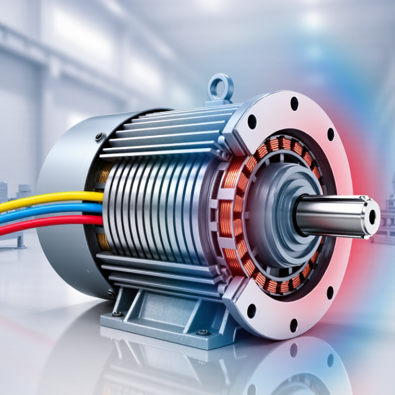
A three-phase motor turns electrical energy into rotation through a coordinated magnetic field. Its stator holds three sets of windings, supplied with alternating currents spaced 120 electrical degrees apart. These currents create a rotating magnetic field inside the motor. The rotor, mounted on a shaft, follows that field and produces useful torque. The air gap is small, but it matters: dust, damage, or poor alignment can affect performance.

The supply frequency shapes motor speed. A motor’s synchronous speed is calculated as 120 × frequency ÷ the number of poles. For a four-pole motor, that equals 1,500 rpm at 50 Hz and 1,800 rpm at 60 Hz; an induction motor runs slightly slower under load. The U.S. Department of Energy’s 2014 Improving Motor and Drive System Performance sourcebook estimates that motor-driven systems use about 68% of U.S. manufacturing electricity. That figure covers systems, not motors alone. Frequency is only part of the story: load, voltage, and motor design also affect actual operation.

Tips: Check the motor nameplate before connecting it to a 50 or 60 Hz supply. Confirm its rated voltage and frequency, then match protection settings to the application. A small oversight can become an expensive one.

What Is a Three-Phase Motor and How Does It Work?

Main components: The stator’s windings create a rotating magnetic field when supplied with three-phase AC. This field induces current in the rotor, producing torque. The chart compares common supply frequencies: 50 Hz means 50 cycles per second, while 60 Hz means 60 cycles per second. For the same number of motor poles, synchronous speed is proportional to supply frequency.

How 120° Phase Spacing Creates a Rotating Magnetic Field

A three-phase motor turns electrical timing into mechanical motion. Inside the stator, copper windings are arranged to create magnetic poles around the rotor. Their currents peak at different times, separated by 120 electrical degrees. That spacing matters. As the magnetic pull from one phase grows, the next phase takes over, followed by the third. Together, the changing fields sweep around the stator instead of simply pulsing in place. Imagine three people pushing a wheel in sequence. It is an imperfect analogy, but it shows why the motor gets a steady turning force.

With a balanced supply, the three magnetic contributions combine into a rotating field with nearly constant strength. This field cuts across conductors in the rotor and induces current in them. The rotor’s own magnetic field then interacts with the stator field, producing torque. In an induction motor, the rotor runs slightly slower than the rotating field; that difference is needed to keep inducing current. It never quite catches up. Under heavier load, the difference usually increases a little.

The 120-degree spacing is electrical, not always the same as the physical distance between winding groups. The distinction is easy to miss. In motors with multiple pole pairs, the winding layout can cover several physical sections while preserving the required electrical relationship. Swap the order of two supply phases, and the rotating field reverses direction, so the rotor turns the other way. The neat diagrams often show a perfectly smooth field, though real motors have small variations from winding layout and load.

Speed and Slip: A 4-Pole Motor Runs Below 1,500 rpm at 50 Hz

At 50 Hz, a four-pole induction motor has a synchronous speed of exactly 1,500 rpm: 120 times frequency, divided by pole count.

But its rotor must turn more slowly to keep current flowing and produce torque. That difference is slip. Not a fault.

For example, a motor running at 1,465 rpm has 35 rpm of slip, or about 2.3% of synchronous speed. The U.S. Department of Energy’s Improving Motor and Drive System Performance: A Sourcebook for Industry explains that induction-motor speed falls as load increases.

In practice, a technician can compare a motor’s nameplate speed with a tachometer reading under operating load. A fan, pump, or conveyor may show a different reading as its workload changes.

The exact speed depends on the motor’s design and load, so 1,465 rpm is an example, not a universal rating. IEC 60034-1 provides the framework for motor rating and performance specifications; the nameplate remains the practical reference.

One small wrinkle: voltage, temperature, and measurement conditions can also affect readings. Check the setup before treating a few rpm as a problem.

Motor Types and Ratings: Induction, Synchronous, and IEC Efficiency Classes

Three-phase motors are commonly built as induction or synchronous machines. In an induction motor, the stator’s rotating magnetic field induces current in the rotor, producing torque. The rotor turns slightly slower than that field; this difference is called slip. Synchronous motors run in step with the rotating field, so speed depends on supply frequency and pole count. They can suit applications needing precise speed, while induction motors are often valued for rugged construction and straightforward operation. The International Energy Agency’s 2011 report, Energy-Efficiency Policy Opportunities for Electric Motor-Driven Systems, estimates these systems use roughly 45% of global electricity. That scale matters.

IEC efficiency classes help compare motor losses. IEC 60034-30-1 defines IE1, IE2, IE3, and IE4 classes, from Standard to Super Premium Efficiency. A higher class generally means less energy lost as heat, but the label alone does not predict a site’s energy bill. Check the rating plate for output power, voltage, frequency, speed, and duty. Match these details to the driven load and operating hours. A motor running a lightly loaded pump may perform differently from one tested near its rated load. Small detail, big difference. Efficiency comparisons also depend on the applicable test method and motor specification, so compare like with like.

FAQS

What makes a three-phase motor different from a single-phase motor?

It uses three alternating currents, spaced 120 electrical degrees apart. Together, they create a rotating magnetic field. The result is steady rotation.

How does an induction motor produce torque?

The stator’s rotating field induces current in the rotor. That current creates torque, turning the shaft. The rotor usually runs a little slower than the field.

What does “slip” mean in a motor?

Slip is the speed difference between the rotating magnetic field and the rotor. It changes with load and motor design. Real motors are not perfect diagrams.

What speed can a four-pole motor reach?

Its synchronous speed is 1,500 rpm at 50 Hz and 1,800 rpm at 60 Hz. An induction motor runs slightly slower under load.

What are the stator and rotor?

The stator holds the windings that create the magnetic field. The rotor sits on a shaft and follows that field. The narrow air gap matters.

How do induction and synchronous motors differ?

An induction motor’s rotor turns slightly slower than the field. A synchronous motor turns in step with it, with speed linked to frequency and pole count.

What should I check before connecting a motor?

Read the nameplate for rated voltage and frequency. Check that the supply matches, and set protection for the application. Small oversights can be costly.

What do motor efficiency classes tell you?

Classes such as IE1 through IE4 help compare motor losses. Higher classes generally lose less energy as heat, but the label alone cannot predict energy costs.

Why do load and operating hours matter?

A lightly loaded pump may use energy differently from a motor near its rated load. Longer operating hours make small efficiency differences more significant. It is worth checking.

Conclusion

A Three Phase Motor converts electrical energy into mechanical rotation using three alternating currents spaced 120 degrees apart. Its main parts are the stator, which holds the windings, and the rotor, which turns inside the stator. When supplied with 50 or 60 Hz power, the three currents work together to produce a rotating magnetic field. This field interacts with the rotor and creates torque, making the motor useful for many industrial and commercial applications.

Motor speed depends on the supply frequency and the number of poles. At 50 Hz, a four-pole motor has a synchronous speed of 1,500 rpm, while an induction motor typically runs slightly slower because of slip. A synchronous motor, by contrast, runs in step with the rotating field under its intended operating conditions. Motor selection also involves considering the motor type, operating requirements, and IEC efficiency class, which indicates how effectively electrical input is converted into useful output.

Isabella

Isabella

Isabella is a dedicated marketing professional with a sharp focus on driving brand growth and engagement through strategic content creation. With an extensive background in digital marketing, she combines her passion for storytelling with her keen understanding of industry trends to deliver......