How to Choose the Right Robotics Motor for Your Needs?

Time:2026-09-29 Author:Sienna
0%

Choosing the right Robotics Motor begins with the machine’s real movement, not a product label. A motor that looks powerful may stall when acceleration, friction, and payload combine. Engineers should measure required torque, speed, duty cycle, voltage, and available space. Small details matter. A 3-kilogram arm can demand sharp torque peaks near full extension. A conveyor may require steady torque for eight hours. These conditions lead to different motor choices.

Reliable selection also depends on the drive system around the motor. Check the controller’s current limits, encoder compatibility, gearbox efficiency, and cooling method. Read the manufacturer’s torque-speed curves carefully. Do not rely only on the advertised maximum torque. That figure may describe a brief peak, not continuous operation. A practical safety margin helps, but excessive oversizing increases cost, weight, and energy use. There is no perfect motor. There is only a suitable balance.

Testing should confirm the calculations. Mount the motor with the intended gearbox, apply the expected load, and monitor temperature during repeated cycles. Listen for vibration. Watch for missed steps, unstable feedback, or slow acceleration. A neat spreadsheet can still miss a hot bearing or a poorly matched controller. That is where this process becomes less certain, and more useful. Recheck assumptions before finalizing the design. Consult current datasheets and qualified engineers when safety, precision, or high-power motion is involved. The best Robotics Motor is not the strongest model available. It is the one that performs reliably under your actual conditions.
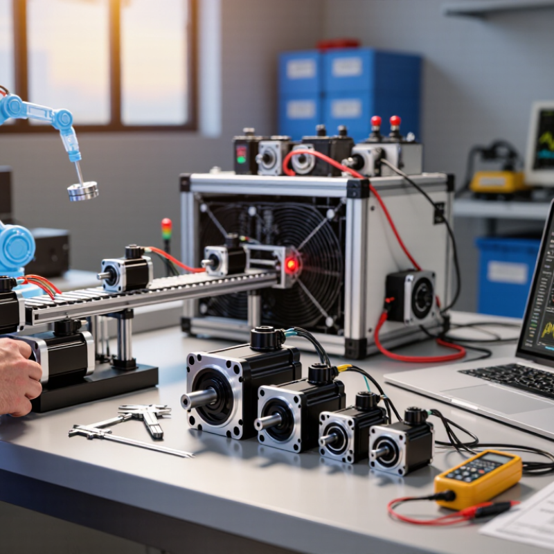
How to Choose the Right Robotics Motor for Your Needs?

Define Payload Torque, Speed, and a 20–30% Safety Margin

A motor should be sized around the real load, not the payload number alone. Include the gripper, brackets, cables, and any part the robot carries. For a horizontal arm, estimate static joint torque with load mass × gravity × distance from the joint. An 8 kg load held 0.25 m out creates about 19.6 N·m, before tool weight, acceleration, or friction. Small details matter.

Add a 20–30% safety margin to the calculated requirement, then check the motor’s continuous and peak torque at the intended speed. That example calls for roughly 23.5–25.5 N·m before accounting for omitted loads; it is not a final motor rating. A motor may produce high peak torque briefly but overheat under continuous demand. Check the torque-speed curve, duty cycle, gearbox limits, and stopping demands. A neat spreadsheet can still miss cable drag. Recheck the assumptions.

The International Federation of Robotics’ World Robotics 2024 report recorded 541,302 industrial robot installations in 2023. That scale makes careful sizing practical, not academic: undersized motors can stall, while oversized systems add cost and inertia. Set speed from the task cycle, including acceleration and settling time, rather than choosing the fastest catalog figure. Leave room for uncertainty. The 20–30% margin is a starting point, not a universal rule; validate it against the mechanism, operating temperature, and manufacturer data.

Compare DC, BLDC, Servo, and Stepper Motors by Efficiency and Control

Choosing a robotics motor starts with the motion it must deliver. A small wheeled robot may need steady rotation, while a camera arm needs precise positioning. Efficiency also depends on load, speed, gearing, and the motor driver. A motor that looks efficient on paper can waste energy when poorly matched.

Brushed DC motors are simple to control with voltage or pulse-width modulation. They suit cost-conscious projects, but brush wear means periodic maintenance. BLDC motors avoid brushes and often deliver better efficiency at sustained speeds. They need an electronic controller, which adds setup work. Listen for noise, too. A poorly tuned controller can create rough motion.

Servo systems pair a motor with feedback, making them useful for controlled angles, speed, or torque. Their accuracy depends on sensor quality and tuning, not just the motor itself. Stepper motors move in discrete increments and can hold position without a separate feedback sensor. That is convenient. Yet they may lose steps under heavy loads, and holding still can draw substantial current. In a small test, compare current draw and temperature at the actual working load, not only during unloaded spinning. The neat categories blur in real machines; gearing and control settings can matter as much as motor type.

Match Gear Ratios to Output Torque, Speed, and 50:1–160:1 Harmonic Drives

How to Choose the Right Robotics Motor for Your Needs?

A robot motor should match the load at the joint, not just its rated wattage. Calculate output torque as motor torque multiplied by gear ratio and efficiency. A 50:1 harmonic drive can deliver strong torque in a compact joint, while a 160:1 ratio suits heavier, slower axes. The trade-off is clear: higher ratios reduce output speed and may increase heat. IFR’s World Robotics 2024 report recorded 541,302 industrial robot installations in 2023. That scale highlights a practical lesson: small selection errors can multiply across production lines. Choose a motor with enough continuous torque, not only peak torque. Peak ratings can mislead.

For a joint moving 30 revolutions per minute, a 160:1 reduction may be unnecessarily slow. A 50:1 ratio could preserve responsiveness while meeting torque demand. Check reflected inertia, duty cycle, and holding torque during sudden stops. Harmonic drives typically offer low backlash, but efficiency varies with load, lubrication, and speed.

The U.S. Department of Energy’s Industrial Motor Systems Market Assessment notes that motor systems can account for a major share of industrial electricity use. Efficiency deserves attention. More torque is not always better.

Tips: Measure the real load first. Add a safety margin of 20–30%, then validate it through thermal testing. Record temperature after repeated cycles. A cool motor on paper may run hot in the enclosure. I have seen calculations fail because cable drag and acceleration were ignored. Recheck the model. Reality is untidy.

Cite: International Federation of Robotics, World Robotics 2024; U.S. Department of Energy, Industrial Motor Systems Market Assessment.

Choose Encoder Resolution Using ISO 9283 Accuracy and Repeatability Metrics

Choose encoder resolution against the robot’s measured task performance, not as a stand-in for accuracy. ISO 9283:1998 defines test methods for pose accuracy, pose repeatability, path accuracy, and path repeatability. These measurements describe what the robot achieves at its tool, under specified test conditions. Encoder counts describe how finely its position is represented internally. Not the whole story.

For example, a 17-bit encoder paired with a 100:1 reducer gives a theoretical output increment of about 0.000027 degrees. That figure excludes backlash, structural flex, thermal drift, and control errors. A finer encoder cannot erase them. Use ISO 9283 results under loads, speeds, and workspace positions close to your application, then compare repeatability with the tightest placement tolerance. A practical check: track a tool point across repeated moves and inspect the spread, not only its average position. IFR’s World Robotics 2024 report recorded 541,302 industrial robot installations in 2023, highlighting the scale of automation where performance claims matter. Still, test reports rarely reproduce every production condition. That gap deserves attention; it is easy to over-specify the encoder and overlook the joint mechanics.

How to Choose the Right Robotics Motor for Your Needs?

Choose Encoder Resolution Using ISO 9283 Accuracy and Repeatability Metrics

The chart shows theoretical angular increments at a robot joint using a 100:1 reduction ratio. Counts per revolution are effective decoded counts; output increment is calculated as 360° ÷ (counts per revolution × 100). Higher resolution gives a smaller encoder step, but does not by itself guarantee better robot accuracy or repeatability. Use ISO 9283 test results for the complete robot to set application requirements, then select an encoder whose quantization is suitably smaller than the measured repeatability.

Verify Thermal Limits with IEC 60034-1 Duty Types S1–S9

How to Choose the Right Robotics Motor for Your Needs?

Verify Thermal Limits with IEC 60034-1 Duty Types S1–S9

Choosing a robotics motor means checking heat, not just peak torque. The U.S. Department of Energy’s 2014 report, Improving Motor and Drive System Performance, estimates that motor-driven systems use about 70% of industrial electricity. That makes duty-cycle selection more than a sizing detail. IEC 60034-1 classifies operating patterns, helping engineers assess how load and rest periods affect motor temperature.

70% motor-driven systems use about 70% of industrial electricity.

S1 describes continuous operation at steady load; S2 covers short-time operation followed by rest. S3 represents repeating load and rest periods, while S4 and S5 include starting and, in S5, electric braking. S6–S8 cover continuous cycles with changing loads, speeds, or braking. S9 addresses non-periodic changes in load and speed. A stop-start robot should not be called S1 just because its average torque looks low. Heat builds during acceleration and holding, too.

Record the real cycle: payload, acceleration, dwell time, braking, ambient temperature, and cooling airflow. Compare measured or estimated winding temperatures with the motor’s rated limits for the selected duty type. Allow margin for warm enclosures and frequent stops.

A tidy spreadsheet can still miss a blocked fan or nearby heat source. That deserves another check. Confirm the duty rating against IEC 60034-1 and the motor’s test data; peak torque alone cannot establish thermal suitability.

FAQS

How should I choose between DC, BLDC, servo, and stepper motors?

Match the motor to the motion, load, and required control. Brushed DC motors are simple and often suit cost-conscious projects. BLDC motors avoid brush wear but need an electronic controller. Servo systems use feedback for controlled movement. Steppers move in fixed increments, but heavy loads can make them miss steps.

Which motor type is usually more efficient?

BLDC motors often perform efficiently at sustained speeds. Actual efficiency depends on load, speed, gearing, and driver settings. Test the motor under its real working load. Paper ratings can mislead.

When is a servo system useful?

Choose a servo when you need controlled angle, speed, or torque. Its accuracy depends on sensor quality and tuning. A good motor alone is not enough.

Can a stepper motor hold a position without feedback?

Yes. Steppers can hold position without a separate feedback sensor. However, they may lose steps under heavy loads. Holding still can also draw substantial current. Check the temperature.

How do gear ratios affect speed and torque?

A higher reduction ratio can increase output torque while reducing speed. For example, a 50:1 ratio may suit a responsive joint. A 160:1 ratio may better fit a heavier, slower axis. More reduction is not always better.

How can I estimate a geared motor’s output torque?

Multiply motor torque by the gear ratio and the drive’s efficiency. Then compare the result with the joint’s real load. Include acceleration and cable drag; I might still miss a detail.

What should I check before selecting a motor for a robot joint?

Measure the actual load, duty cycle, reflected inertia, and required speed. Choose enough continuous torque, not just peak torque. A 20–30% safety margin can help, but testing matters more.

How do I check whether the motor will overheat?

Run repeated cycles at the real load and record the temperature. Test it inside the intended enclosure. A cool motor during unloaded spinning proves little. Measure, then reconsider.

Conclusion

Choosing the right Robotics Motor begins with defining the load, required speed, and operating conditions. Calculate the torque needed to move the payload, then include a 20–30% safety margin to allow for acceleration, friction, and changing loads. Compare DC, BLDC, servo, and stepper motors in terms of efficiency, controllability, and positioning needs. A motor that offers precise control may suit a task requiring accurate motion, while other applications may prioritize simple operation or energy efficiency.

Next, select a gear ratio that delivers the required output torque and speed; harmonic drives in the 50:1–160:1 range can be considered when substantial reduction is needed. Choose encoder resolution based on the required positioning accuracy and repeatability, using ISO 9283 metrics as a reference. Finally, check that the motor can handle its thermal demands over the intended operating cycle. IEC 60034-1 duty types S1–S9 help describe these patterns and support a reliable choice.

Sienna

Sienna

Sienna is a skilled marketing professional with a deep expertise in our company’s core products and services. With a passion for innovation and detail, she plays a pivotal role in crafting insightful blog posts that not only highlight the unique features of our offerings but also provide valuable......